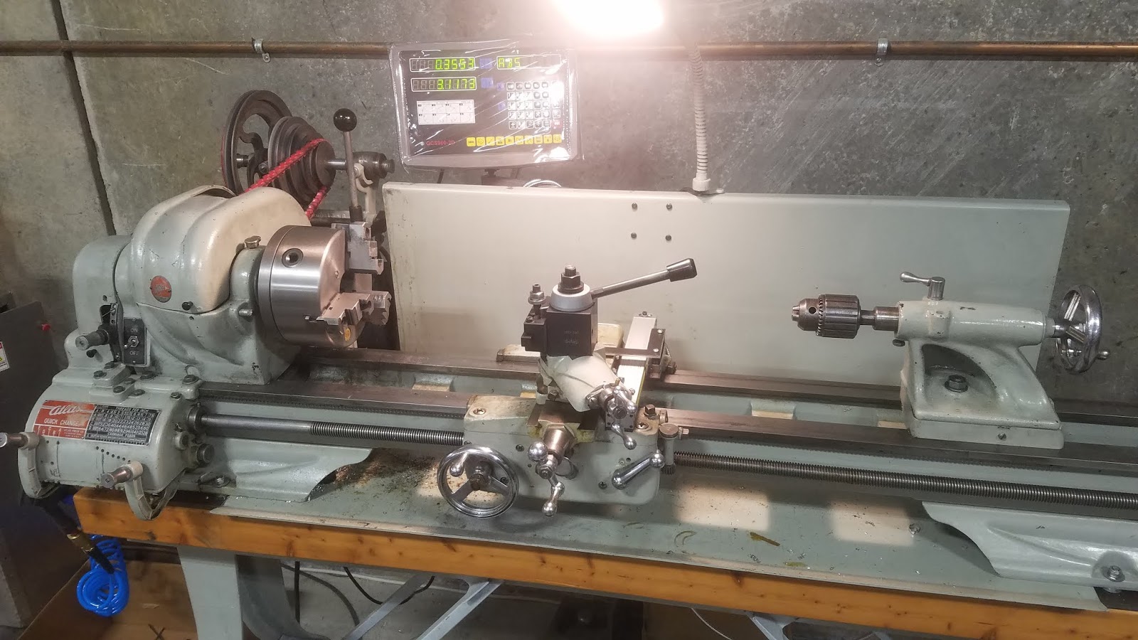
Perhaps I could 'CNC' the lathe - that is, control the carriage movement using a computer. There are probably 25 gears in there and they are very expensive. Perhaps I could just build the QCGB? Nope - while it would be rewarding, the cost would be prohibitive. If I bought one, it would be quite a project to connect it to my lathe my lathe was never made to have a QCGB. The bad news is that I don't have a QCGB. Those gears were selected from a stack of gears, according to a chart, in order to produce the desired ratio. In this picture, the four gears at the bottom (look sharp to see the 4th!) are the change gears. In the old days, the ratio between the spindle and lead screw was set by elaborate combinations of individual change gears. If the spindle makes 20 revolutions and the carriage moves 1", a 20 TPI thread will be produced. The gear train controlled the ratio of spindle turns to lead screw turns, and by extension the the ratio of spindle revolutions to carriage movement. The reason is that the operator configured the lathe so the spindle was connected to the lead screw using a carefully selected gear train. What made the cutter find just the right spot to begin? Why did it cut that rather coarse thread instead of a fine thread? Why did it cut a thread at all, and not produce a cylinder? (In that video, the camera is mounted to the carriage. Here's a link to a classic video showing this in action: One of the neatest capabilities of a lathe is the ability to cut screw threads.

Listen carefully for 'quick change gear box' and 'lead screw.'

I'll refer you to Tubalcain, a well regarded instructor. To understand what I am doing, you have to know some basics of lathes. Today I'll begin something a little different - I'll post about creating an accessory for this lathe to simulate a quick change gearbox (henceforth, QCGB.) I've posted about my adventures with restoring my 1937 Craftsman 12" lathe.


 0 kommentar(er)
